2/18/2021 Update -- The module discussed in this blog post has officially been renamed blockmeshbuilder as of February 15, 2021. It is still hosted on Github.
The Meshing Process
When using CFD to solve a problem, the analyst has many decisions to make which will determine the speed and accuracy of the solution. Arguably, the vast majority of these decisions are made when constructing the CFD mesh. More often than not, the majority of person-hours spent setting up a CFD simulation are devoted to constructing the computational mesh. At the same time, some CFD solvers either struggle with, or are unable to handle certain types of mesh elements. For example, it is well known that solvers often have accuracy issues when solving tetrahedral mesh elements in the boundary layer region.
Given these requirements, the software used to generate CFD meshes must strike a balance between automation and user control over the final result. Popular commercial software, like the ANSYS Meshing tool, tend to favour ease of use by having a high degree of automation, while other software, like gmsh, opt to give the user more control at the expense of being more difficult to use.
The Value Proposition of blockMesh
blockMesh, one of the meshing softwares packaged with all modern releases of OpenFOAM1, falls on the extreme ‘user-control’ end of the aforementioned spectrum, to the point where a user could directly compute the positions of every node in the mesh in advance. This is only possible because of a major constraint: the mesh structure must be specified using only hexahedral block structures, which are themselves divided into regular hexahedral elements1. Because the mesh structure is highly organized, meshing is fairly quick compared to algorithms for generating tetrahedral or hybrid meshes.
Many simple geometries, such as airfoils or pipes naturally lend themselves to block-structured meshing, while more complex geometries (especially those with sudden contractions or expansions along the primary flow path) suffer from issues relating to differing grid densities in one region requiring refinement in other regions. Geometries in the former category are plentiful enough to warrant the use of a dedicated block-structured approach to meshing, and can be meshed in a straightforward manner using blockMesh. Meshing strategies for geometries in the latter category will surely be addressed in future blog posts.
Using blockMesh
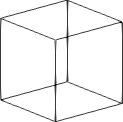
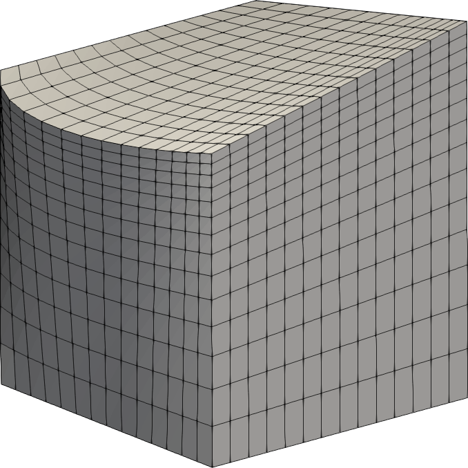
The commands used to specify the mesh details for the blockMesh program, are written to a file, often called blockMeshDict, located in the system folder of the OpenFOAM case folder. See our blog article on the OpenFOAM case structure for more information. The full set of commands available to specify a blockMeshDict are provided elsewhere. Essentially, a list of nodes is provided, followed by a series of commands which construct blocks from those nodes, project edges and faces to simple geometries, and specify the boundary patches. A hexahedral wireframe element belonging to a hex block is shown in figure 1.


Figure 1: A single wireframe element and a structured hex block created using blockMesh
The Problem with the blockMeshDict
Here is the command to create a single hex block:
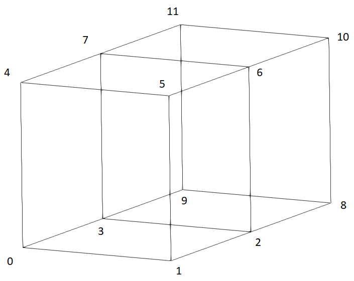
hex (0 1 2 3 4 5 6 7) (14 14 14)where the numbers in the first set of parentheses are the node labels (these have been defined in a list earlier in the file), and the numbers in the second parentheses are the number of divisions of the block in each direction. The nodes must be ordered in a specific way, so that the orientation of the block is fully defined according to this image. The trouble starts when 2 or more hex blocks need to be defined. Figure 2 depicts the new scenario.

Figure 2: The node ordering required for two blocks stacked along the y-axis with a shared face
    hex (0 1 2 3 4 5 6 7)  (10 14 12)
    hex (3 2 8 9 7 6 10 11)  (10 14 12)
The nodes 3, 2, 7, and 6 are shared between the 2 blocks, and they comprise a face shared by both blocks. The merging of these blocks is done behind-the-scenes by blockMesh, which is a welcome feature. However, the process can easily go awry when just two node labels are listed out of order in the hex block definitions, causing blockMesh to fail (where the most it can tell you is which block is giving it trouble). You might be able to sort out what went wrong using the linked diagram above, and by sketching out the block structure while labeling each node, but the debugging process becomes increasingly daunting when 5, 10, or more interconnected blocks are in play. Specifying constraints on edges and faces, and also defining boundary patches becomes unruly in a hurry. Moreover, the blockMeshDict file tends to become fragile: breaking blocks partway through a project can be incredibly tedious because hex block definitions require their node list to be adjusted correctly.
Accelerating the Process using ofblockmeshdicthelper
Fortunately, the aforementioned difficulties can be avoided by using a Python helper library called ofblockmeshdicthelper, originally written by the github user takaakiaoki, and heavily modified and extended by me. The library allows Python users to specify the commands in the blockMeshDict file programmatically. Critically, the library is compatible with the widely-used Python numerics library, numpy. The best way to start is with an example. Here we write a simple program to generate a mesh for the lid-driven cavity problem… with a twist.
#Import numpy module and required classes from helper library
import numpy as np
from ofblockmeshdicthelper import BlockMeshDict, CartBlockStruct, SimpleGradingElement, Boundary

#Initialize the blockMeshDict container, and set the working units
bmd = BlockMeshDict()
bmd.set_metric('mm')

#Create the arrays to define the block structure. The length of each array minus one is the number of blocks stacked in that direction, while the values, listed in ascending order, are the corresponding co-ordinates of the block vertices
xs = np.array([0.0,0.2,0.4,0.6,0.8,1.0]) - 0.5  #Five evenly divided blocks along the x-axis
ys = xs.copy()                       #The same along the y-axis
zs = np.array([0.0,0.01])           #One block of thickness 0.01 mm along the z-axis

ndx = np.full_like(xs,14)           #Each block in the x-direction has 14 divisions
ndy = ndx.copy()
ndz = np.array([1,0])               #Each block is 1 element thick in the z-direction

#The CartBlockStruct builds the 3D array of block vertices, edges, faces, grading, and more so that the basic block structure can be further manipulated to produce more sophisticated meshes
cavity = CartBlockStruct(xs,ys,zs,ndx,ndy,ndz)

#Get the grading array, and assign simple mesh density gradients across multiple blocks using a single command
GD = cavity['grading']
edge_grd = 4
GD[:,0,:,1] = SimpleGradingElement(edge_grd)    #bottom
GD[:,-2,:,1] = SimpleGradingElement(1/edge_grd) #top
GD[0,:,:,0] = SimpleGradingElement(edge_grd)    #left
GD[-2,:,:,0] = SimpleGradingElement(1/edge_grd) #right

#Grab the arrays of x and y co-ordinates
vts = cavity['vertices']
XS,YS = vts[:,:,:,0],vts[:,:,:,1]
#Transform the arrays into polar form
RS = np.sqrt(XS**2 + YS**2)
TS = np.arctan2(YS,XS)

TS[1:5,1:5,:] += np.pi/8 #Rotate interior blocks by 22.5 degrees
TS[2:4,2:4,:] += np.pi/8 #Rotate innermost block by a further 22.5 degrees

#Transform the values back and assign the new values to the pre-existing sub-arrays
XS[:] = RS*np.cos(TS)
YS[:] = RS*np.sin(TS)

#Write the cavity block-structure to file
cavity.write(bmd)

#Collect the boundary faces and create a patch called ‘lid’ to be referenced by the CFD code
lid_faces = cavity['faces'][:-1,-1,:-1,1].flatten()
bot_bnd = Boundary('patch', 'lid', faces=lid_faces)
bmd.add_boundary(bot_bnd)

#Write the blockMeshDict file
with open(r'blockMeshDict','w') as infile:
    infile.write(bmd.format())
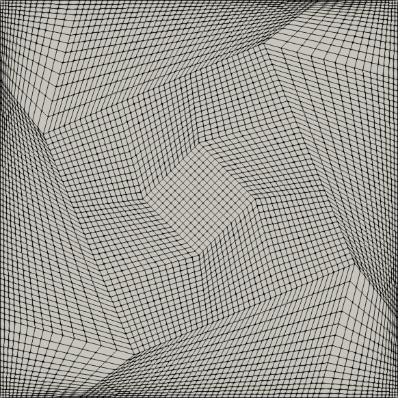
After running the above code and moving the blockMeshDict file into the system folder of an OpenFOAM case folder, the mesh can be generated using the blockMesh command, and the result can be viewed in Paraview, the view along the -z axis is shown in figure 3.

Figure 3: The lid-driven cavity mesh with the internal blocks twisted by 22.5 and 45 degrees respectively
The grading towards the edges of the mesh is accomplished using just four lines of code, while the twisting behaviour is done in 8 lines. The purpose of each line of code is clear, and changes can be easily made to the entire structure. For example, the entire structure can be made 2 blocks deep by including 1 additional element to the arrays in lines 12 and 16. The best part is that the node ordering for the hex block definitions is done automatically. In addition, the above code (with comments) is only 53 lines, while the generated blockMeshDict file is nearly triple the length, at 151 lines.
The real star of the show, which allows the above code to be so compact, is the indexing capabilities of numpy arrays. In each case, the first three indices select elements along the x,y,and z axes, respectively. A fourth index is used to indicate which component at that location to modify. For example, the line cavity['vertices'][-1,0,:,0] += 0.1 would shift the two block vertices in the bottom right corner of the above image 0.1 mm to the right.
Just Getting Started
The last example only showcased some of the features available using the ofblockmeshdicthelper library. Some other available methods allow for tight control of edges and faces, and blocks can be masked to easily create stepped geometries. New features are also planned for the library. Expect to see more blog entries on ofblockmeshdicthelper in the future.
What meshing tools do you like to use for CFD problems? What meshing features would you like to be able to use, but it seems no one has developed them yet?
About the Author
Nolan Dyck, MESc, is a co-founder and CTO of Maple Key Labs. He is a PhD candidate at Western University where he focuses on modeling rotating, compressible flows in the Ranque-Hilsch Vortex Tube, to better understand the temperature separation process. He applies both analytical approaches using simplified versions of the Navier-Stokes equations, and numerical methods using Ansys CFX software to predict temperature separation. He is also the author of a Python library called ofblockmeshdicthelper used to automate the process of creating BlockMeshDict files for the blockMesh meshing tool. During his master’s studies, he developed a new technique for generating and analyzing randomized digital samples of spherical-void-phase porous media using the discrete element modelling code YADE, Solidworks, and CFX.
1 The other mesh software provided with OpenFOAM is snappyHexMesh
2 Neighbouring, parallel block edges can be made coincident to create a wedge-block structure with a single row of triangular prism elements along the coincident edges, which is helpful in a few cases.

