Introduction
Fluid jets are found in many engineering applications including rocket nozzles and cooling devices, but may also arise due to accidental leaks. When the fluid is a gas, relatively low pressures are required for the jet to reach the speed of sound (Mach 1) at the exit of the nozzle. As such, it’s important to consider compressibility effects on the behaviour of the jet. This results in what's commonly known as a choked flow condition wherein the mass flow through the nozzle becomes independent of downstream fluid properties. As such, the flow is fully defined by the upstream conditions and nozzle geometry. This flow configuration reveals a number of interesting phenomena, which may or may not be desired in a given application. Understanding how choked flow behaviour impacts the nozzle performance, flow rate, and downstream conditions can be important to understand in many applications. This article will explore the various types of jets that can form in a choked flow nozzle, some of the physics that can be used to understand their behaviour, and the considerations that are required to study these systems using CFD. Only a converging nozzle will be explored in this post, however, the basic principles can be applied to converging-diverging nozzles (in case you’re intent on building a rocket engine).
Physics of Choked Flow Nozzles
Choked flow nozzles can be grouped into three main categories based on the pressure of the flow as it exits the nozzle, these are:
- Over-Expanded
- Properly Expanded
- Under-Expanded
An over-expanded jet occurs when the pressure at the nozzle is below ambient pressure, properly expanded is when the nozzle pressure is equal to ambient pressure, and under-expanded nozzles is when the pressure is greater than ambient. Under-expanded jets are the most common type of nozzle and will be the type considered from here on.

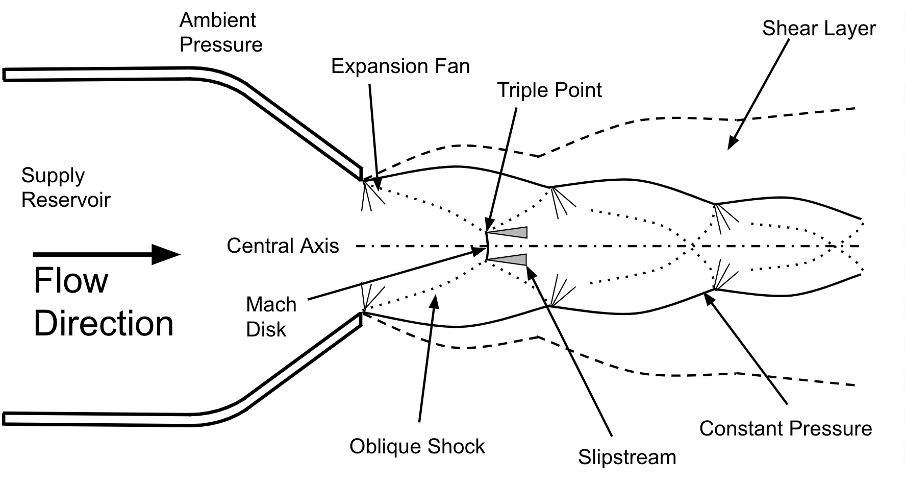
Figure 1: Basic structure of an Under-Expanded Jet
The basic flow structure of any under-expanded jet is shown in figure 1. In this figure, a high pressure gas in the supply reservoir is free to flow along the central axis toward an ambient pressure environment, through a converging nozzle. As the flow moves through the converging portion of the nozzle, the pressure will decrease and the velocity increase until it reaches the exit. If the supply pressure is above the critical limit (calculated using P_\text{cr}/P = \left[(\gamma+1)/2\right]^{\gamma/(\gamma-1)}, where P_\text{cr} is the critical supply pressure, P is the nozzle exit pressure, and \gamma is the ratio of specific heats), then velocity at the nozzle will reach Mach 1. As the jet leaves the nozzle the pressure of the gas is still above ambient pressure causing the gas to expand and accelerate beyond Mach 1. The flow will contract and decelerate further downstream causing the jet to regain some of its pressure. This creates the most distinct and visually appealing features of these jets, the Mach diamonds. You can see Mach diamonds by watching videos of the space shuttle main engines or the SpaceX Raptor engine test runs as shown in the video below (volume is loud).
The basic relation required for defining an under-expanded nozzle is called the Nozzle Pressure Ratio (NPR). The NPR is simply calculated by dividing the supply pressure by the ambient pressure. The jet structure shown in figure 1 is known as a highly under-expanded free jet, in which the NPR exceeds 3.8. In this case, a small normal shock called a Mach disk is present along the center axis of the jet at the tail end of the first Mach diamond. The Mach disk phenomenon does not exist in free jets where the NPR is less approximately 3.8.
\text{NPR} = \frac{P_0}{P_\text{sim}}Surrounding the supersonic core of the jet is a highly turbulent subsonic region called the shear layer. This region is important to many applications since it is responsible for mixing, acoustics, and the decay of the supersonic core downstream of the nozzle1.
Mass Flow
One of the most important questions you might have about the nozzle you’re working with is “what’s the mass flow?”, since this is one of the main parameters of interest in many applications. Thankfully, this question is relatively easy to answer and can also help shed light on the mechanics of the flow. Mass flow through any pipe can be calculated as the product of flow velocity and pipe area divided by the specific volume, \dot{m} = \frac{UA}{v}. However, this is compressible flow, so it can't be that easy… The pipe area can be determined simply as the exit area of the nozzle, assuming the nozzle is a circle, the area is: A = \pi r^2.
Since the flow at the nozzle is known to be Mach 1, we can determine the velocity by finding the speed of sound at the nozzle exit. As the flow accelerates through the nozzle, it also decreases in temperature, so the speed of sound at the nozzle exit can be solved as5:
\begin{aligned}
U_e &= \sqrt{\gamma R T_e}\\
T_e &= \frac{2T_0}{\gamma+1}
\end{aligned}
Where the subscript “e” indicates that the value is determined at the nozzle exit. Similarly, the specific volume at the nozzle exit can be determined as:
\text{v}_\text{e} =\text{v}_0 \left(\frac{\gamma+1}{2}\right)^\frac{1}{\gamma-1}Using some algebra, the total mass flow through the nozzle can be determined by knowing the inlet condition and nozzle area alone. Alternatively, the specific volume can be determined by knowing the pressure and temperature at the nozzle exit, in which case the mass flow is found using the inlet temperature and pressure, demonstrating how these systems are totally independent of the conditions downstream. Interestingly, this phenomenon can be leveraged to measure mass flow rate (assuming the inlet temperature is constant). This method has substantial pressure losses, but if that is acceptable in your application it can provide a low cost method of monitoring the flow.
CFD of Under-Expanded Jets Using OpenFOAM
CFD modelling of any compressible flow application is more complicated than simulating an incompressible application, as the solver you select must include the energy equation and an equation of state for the gas, in addition to the usual continuity and momentum equations. In OpenFOAM, the most suitable solver available for this application is rhoCentralFoam: a density based solver which helps the solver resolve the sharp discontinuities that are present at shocks. The Mach disk mentioned earlier is an example of a shock discontinuity, which is difficult to resolve with a pressure based solver (trust us… we’ve tried!).
Surrounding the supersonic core of the jet is the shear region, which is characterized by a high degree of turbulence. The shear region is responsible for decay of the supersonic core, and mixing between the jet and ambient fluids. In OpenFOAM, the \text{k}-\omega \,\,\, \text{SST} model is a good option for resolving the average effect of the shear layer, however it will struggle to resolve any coherent instabilities in the flow2,3. If it is important to resolve flow instabilities in your application, a more computationally expensive LES turbulence model can be used to capture more detail in the shear layer.
One limitation when modelling high speed jets with rhoCentralFoam is the time step required to ensure the stability of the solver. Our experience has found that the Courant number in the simulation should be limited to Co = 0.5. This limitation is driven by the high flow speed and small grid spacing required near the nozzle exit and severely reduces the time step of the simulation, resulting in high computational costs. One extremely useful tool for getting around this issue is the OpenFOAM mapFields utility, provided you are not interested in the transient startup behaviour of the jet and only wish to explore the steady state operation. To use mapFields, you would run a simulation of the nozzle with a very coarse grid, such that the time step can be larger and the computational time for each step is reduced. This can be run until the model reaches steady state, at which point the results can be transferred to a grid independent mesh and continued until the results reach steady state again. Another option for reducing the computational cost is to run the simulation with an axi-symmetric model. This will reduce the mesh size considerably, enabling reasonable results to be obtained. Of course, this is only possible if there are no three-dimensional characteristics that would be suppressed by the use of an axi-symmetric domain.
Boundary Conditions
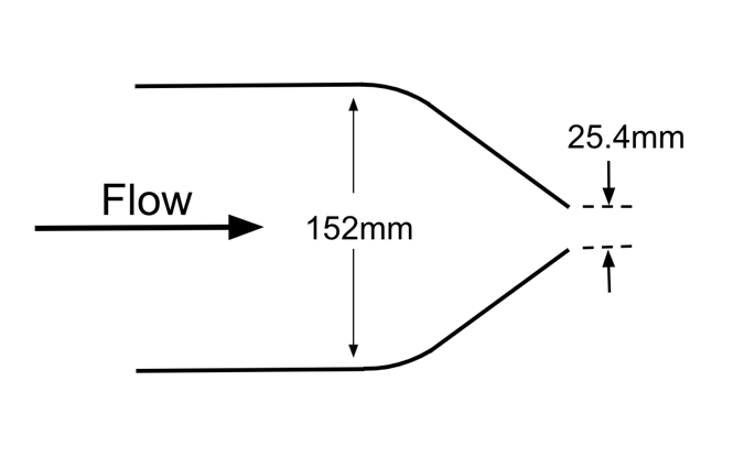
As is the case with all CFD simulations, application of the right of boundary conditions are critical to obtain accurate results. Since the mass flow through the model is totally dependent on only the pressure and temperature at the inlet, the velocity does not need to be stated on any boundary in the domain. This may seem counter-intuitive, but remember that no information from the outlet boundaries can influence the behaviour of the inlet boundaries. The example I will show below uses a nozzle with the geometry in figure 2 and boundary conditions shown in figure 3. You may notice that figure 3 is an axi-symmetric domain, which will be discussed later. Each of the boundary condition types specified at each boundary is provided in the table below. The boundary conditions for any inlet are specified as either totalPressure or totalTemperature which is a compressible variant of the fixedValue condition and takes the fluid velocity into account at the boundary. Some care must be taken when using these boundary conditions to ensure the stagnation pressure and temperature applied is correct.
| Boundary | P | U | T |
|---|---|---|---|
| Inlet | totalPressure |
zeroGradient |
totalTemperature |
| Inlet Freestream 1 | totalPressure |
zeroGradient |
totalTemperature |
| Inlet Freestream 2 | totalPressure |
zeroGradient |
totalTemperature |
| Outlet | totalPressure |
zeroGradient |
zeroGradient |
| Wall | zeroGradient |
noSlip |
zeroGradient |

Figure 2: Case Study Nozzle Geometry

Figure 3: Boundary Conditions Applied
A big concern that may cause issues at the outlet of the domain is pressure oscillations. Since under-expanded jets are extremely loud, sound waves and other pressure waves will need to be dealt with as they interact with the outlet boundaries. Untreated, these waves can reflect back into the domain introducing a source of error. OpenFOAM provides a built in waveTransmissive boundary condition which is designed to allow these waves to pass through without any issue. However, in our experience, this boundary condition is more complicated than it’s worth.
A simpler method of managing waves is to use a coarse mesh near the boundaries to numerically diffuse the waves before they reach the boundary. Simply put, a wave can’t exist if it is smaller than the grid cell itself.
Results
To demonstrate the accuracy of the model discussed above, I ran a simulation and compared it to experimental results4. The experiment created a jet with a NPR = 4.03 and a nozzle diameter of 25.4mm.
To start, a contour plot of the Mach number of the jet can be seen in figure 4. Based on the description provided above, many of the features described in an under-expanded jet can clearly be seen in this model. As the flow moves toward the nozzle exit, the Mach number approaches 1 and suddenly accelerates further as it leaves the nozzle. Further downstream the jet reaches a maximum Mach number of around 2.4, an impressive feat caused by an absolute pressure of only 400 kPa (58 psi).

Figure 4: Contour Plot of the Under-expanded Jet Mach number
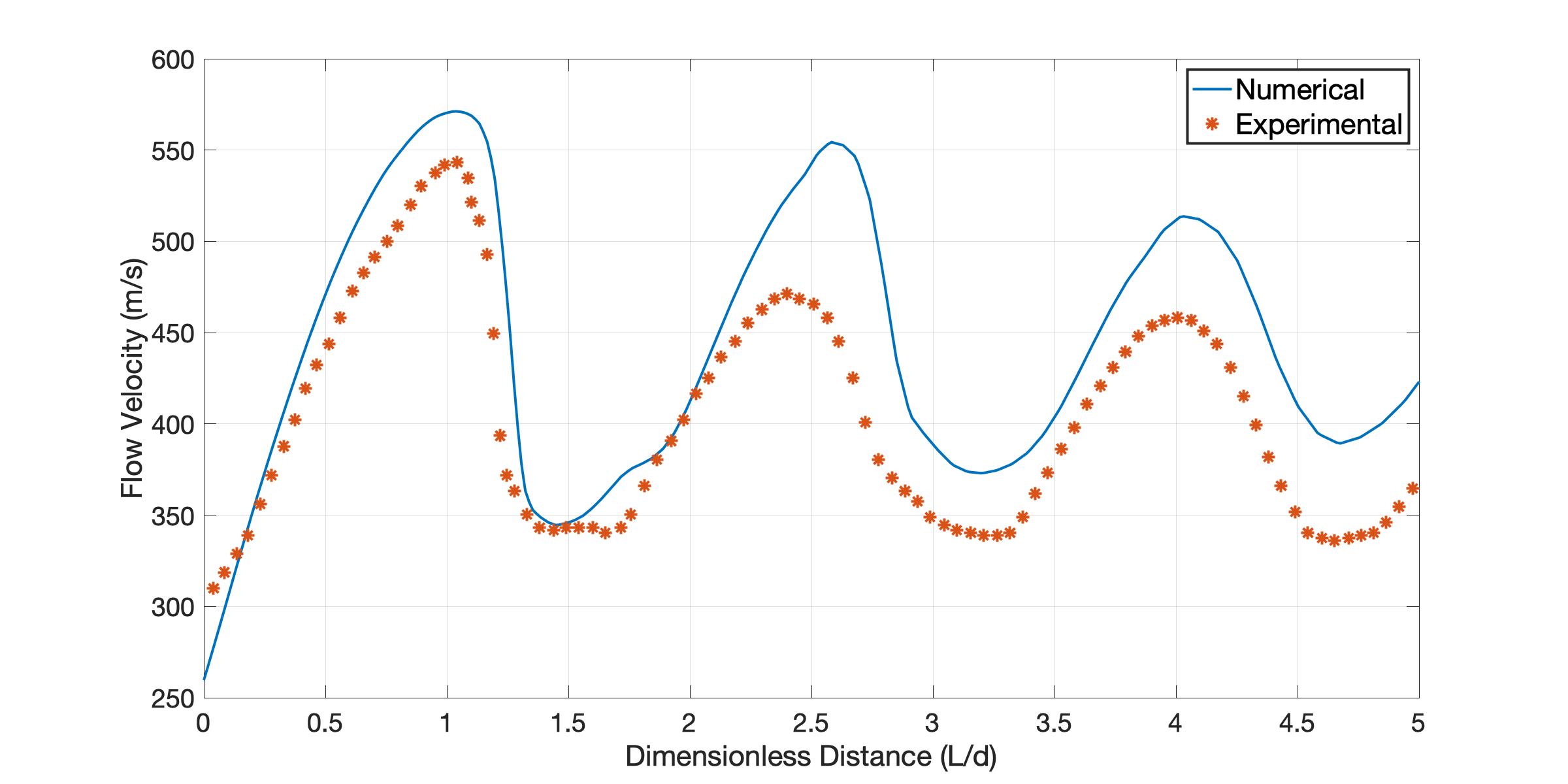
Comparing the velocity at the center of the jet to experiment is shown in figure 5, through the first Mach diamond, the velocity profile is a close match with the experimental results. However, the velocity of the jet in subsequent Mach diamonds exceeds the experimental results. This effect is most likely the result of the k-\omega \,\,\, \text{SST} model incorrectly predicting the absence of a Mach disk near the transition NPR of 3.83, while the Mach disk is clearly present in the experimental study. Since normal shocks are highly irreversible processes, the energy losses in the experimental flow are not captured by this CFD study resulting in higher velocities downstream.

Figure 5: Velocity Profile Comparison between Experimental and Numerical Results
Trusting your CFD
The model explored in this study clearly has some limitations in its predictive ability. While all of the anticipated features in the model were present, the exact behaviour of the jet was lost as a result of some of the simplifications made (i.e. axi-symmetric domain and the turbulence model used). The final results could have been improved through the use of a 3-dimensional model and the LES turbulence model, however it's not always practical to model the full physics present in a flow. This is especially important in transitional regimes of the flow, where seemingly small changes to the simulation can have large impacts on the desired outcome.
Understanding the physics of the simulation is an advantage that can ensure the results don’t just look good, but provide meaningful insight and guide decisions.In complex models of real applications, it’s easy to make reasonable assumptions that have unintended consequences. It would be inappropriate to model this flow with a pressure-based solver, but you could run a stable simulation with results that look acceptable and produce misleading insight. Furthermore, a two-equation turbulence model may or may not be appropriate depending on what part of the simulation is important to your specific application. While these lessons can be learned, they are often an expensive and time consuming exercise. Maple Key Labs has expertise in modelling compressible flows in real world applications. For more information on how we can help, fill out the form on the Contact Us page. For those that want to bring the analysis in-house, we are also available for consultations to ensure clients get started in the right way. By subscribing to our newsletter, you can keep up to date with articles like this.
About the Author
Peter Nielsen, MESc, is a co-founder and CFO of Maple Key Labs. His research was based on using OpenFOAM to model under-expanded impinging jets and apply the techniques within an industry product. Many of the methods used for his research were novel and required extensive validation to ensure they were suitable. He also has several years of industry experience in designing, manufacturing and testing fluid machines.
1 E. Franquet, V. Perrier, S. Gibout, and P. Bruel, “Free underexpanded jets in a quiescent medium: A review” Prog. Aerosp. Sci., vol. 77, pp. 25–53, 2015.
2 B. Zang, V. US, H. D. Lim, X. Wei, and T. H. New, “An assessment of OpenFOAM solver on RANS simulations of round supersonic free jets,” J. Comput. Sci., vol. 28, pp. 18–31, 2018.
3 A. Hamzehloo and P. G. Aleiferis, “LES and RANS modelling of under-expanded jets with application to gaseous fuel direct injection for advanced propulsion systems,” Int. J. Heat Fluid Flow, vol. 76, pp. 309–334, 2019.
4 B. Henderson, J. Bridges, and M. Wernet, “An experimental study of the 81 oscillatory flow structure of tone-producing supersonic impinging jets,” J. Fluid Mech., vol. 542, pp. 115–137, 2005.
5 G.P. Sutton, Rocket Propulsion Elements 9th Edition. Wiley, 2017
